.jpg)


FLIGHT INSTRUMENTS
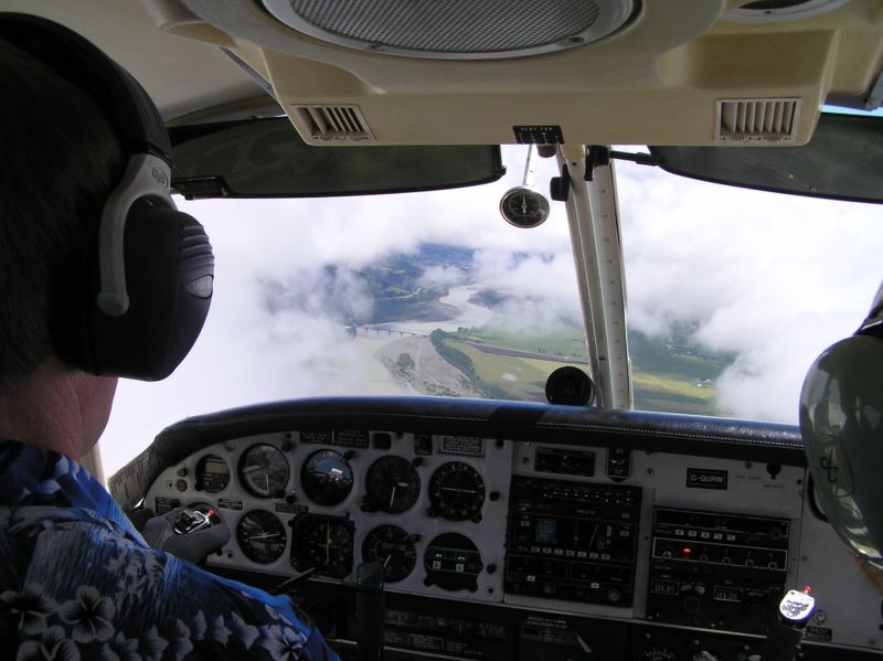
There are two flight-instrument systems, producing two types of flight instruments: pitot-static instruments and gyro instruments.
Pitot-static Instruments
The pitot-static system records static and dynamic air pressure, providing the pilot with information related to airspeed and altitude.
These pressures enter the system by way of ports located on the fuselage (static pressure sources) and the wing (dynamic pressure source).
Of the flight instruments that make use of the pitot-static system—the airspeed indicator, the vertical speed indicator, and the altimeter, only the airspeed is connected to both pressure sources.
Airspeed Indicator
Connected to the static and pitot (dynamic) ports, the airspeed records the pressure difference (speed); each is measured by an expansion box referred to as an aneroid capsule.
In the case that the pitot tube (port) becomes blocked (ice, dust, water, bugs), the airspeed indicator acts like an altimeter and under-reads during a descent, and over-reads during a climb.
There are three primary types of airspeed:
- Indicated airspeed (IAS): uncorrected speed is read from the airspeed indicator. As altitude is increased, the airspeed indicator under-reads approximately 2% per 1000’.
- Calibrated airspeed (CAS): IAS corrected for instrument and installation error; such errors are especially prominent in flights involving high angles of attack. Correction charts are usually found in the Pilot Operating Handbook.
- True Airspeed (TAS): CAS (usually IAS) corrected for air density (altitude and temperature); used primarily for flight planning groundspeed. Pressure altitude (discussed below), temperature, and IAS are entered on the appropriate flight calculator scales. (Note: the scales on E6B computer indicate CAS, rather than IAS, but should be interpreted as IAS for most practical purposes.)
Further Readings: Indicated Airspeed
Airspeed Indicator markings
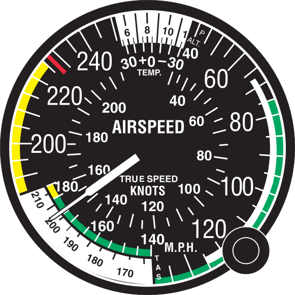
- Red line: never-exceed speed (Vne).
- Yellow arc: caution speed range, never to be intentionally entered, with the upper limit being Vne, and the lower limit being the maximum structural cruising speed (Vno).
- Green arc: normal operating speed range, with the lower limit being the power-off stall speed, including flaps and gear up (Vsl), and the upper limit being Vno.
- White arc: flaps extension speed range—where flaps can be used, with the lower limit being the power-off stall speed with flaps and gear down (Vso), and the upper limit being the “maximum flaps extension speed” (Vfe).
- Note that manoeuvring speed (Va) is not indicated on the instrument.
Further Readings: Airspeed Indicator
Further Readings: Manoeuvring Speed
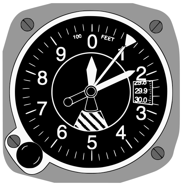
Altimeter
The altimeter is connected only to the static port and also uses an aneroid capsule. It is calibrated on the basis of ICAO Standard Atmosphere assumptions of standard sea level pressure (29.92” Hg), a pressure lapse rate of 1 inch per 1000’, and a standard temperature lapse rate (1.98°C. per 1000’).
In the case that a static port becomes blocked during flight, most aircraft have an “alternate static source” switch in the cockpit that can be selected by the pilot.
If an altimeter indicates a 50’ error when set to the current altimeter pressure setting, the instrument is unserviceable (U/S). During flight the pilot sets the altimeter to the nearest setting source (tower, FSS, etc.).
There are two errors associated with the altimeter: temperature errors and pressure errors. When flying from a high-pressure area to a low-pressure area, the altimeter will read higher than actual altitude; similarly, when flying from warm air to cold air, the altimeter will again read higher than actual altitude.
“From high to low, watch out below.” “From warm to cold, watch out . .”
There are five types of altitudes:
|
Indicated Altitude |
The reading on the altimeter when it is set to the current barometric pressure. |
|---|---|
|
Pressure Altitude |
The reading on the altimeter when it is set to standard pressure (29.92” Hg); this is used primarily in the calculation of aircraft performance and for calculating “true altitude.” |
|
Density Altitude |
Pressure altitude corrected for temperature, used primarily to predict aircraft performance during takeoffs. To calculate, the altimeter is set to 29.92” Hg (pressure altitude) and this figure entered on a flight computer on the appropriate scale. If an altimeter is not available, use the difference between standard pressure and the current altimeter setting; if the current pressure is lower than standard pressure, altitude is increased at a rate of 1000’ per 1-inch difference; if it is higher, the altitude is decreased. Aircraft performance graphs in the Pilot Operating Handbook usually provide a built-in calculation. |
|
True Altitude |
Exact height above sea level. This is used when a pilot wants the most accurate calculation of altitude—for example, when flying over mountainous regions. The current altimeter setting and elevation of the reporting station is noted. The pressure altitude of the aircraft above the reporting station is calculated (not height above sea level)—again using a flight computer—and this is added to the station elevation. |
|
Absolute Altitude |
Height of the aircraft above the surface of earth. Not commonly used, unless the aircraft has radar. |
Further Readings: Altitude
Vertical Speed Indicator
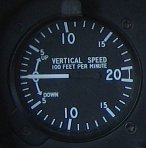
The final pitot-static instrument is the VSI, which indicates the vertical speed of the aircraft in hundreds of feet per minute. The instrument contains “slow bleeding” aneroid capsule; when altitude changes occur, the instrument records a pressure differential; the pressure differential equalizes through a small orifice when the aircraft becomes level.
The VSI is most accurate recording small changes in altitude, but becomes less accurate the greater the rate of descent or climb.
It is connected to the static port, so an alternate means of restoring static pressure for the altimeter if the static port becomes blocked is to deliberately break the glass on the VSI.
Further Readings: Pitot-static Instruments
Gyro Instruments
There are three primary gyro instruments: heading indicator, attitude indicator, and the turn and slip indicator/turn co-ordinator.
All gyros consist of a spinning rotor held in a universal mounting or gimbals.
The spinning of the gyro is powered by two means. The heading indicator and AI are driven by vacuum pressure (engine or venturi). Engine-driven vacuum pressure is included among the pre-takeoff checks whereby the air pressure driving the gyro can be read in inches of mercury (“Hg.). By comparison, the gyros on the turn co-ordinator (or the older turn and slip indicator) is driven by an electric motor; if the electric motor provides insufficient RPMs to the gyro, a “flag” appears on the instrument display.
In conditions of poor to zero visibility, it is impossible to fly an aircraft without flight instruments which depict pitch, roll, and yaw; in cloud, a pilot’s life rests with the correct function of these instruments. The electric/vacuum drive systems provide backup whereby all of the instruments cannot fail simultaneously.
For added security, the gyro instruments are always checked during taxiing before takeoff.
Two principles affect all gyros: gyroscopic inertia (rigidity in space), and precession (perpendicular force on a gyro causes reaction 90° along the rotation direction).
The gyro for the heading indicator spins around a horizontal axis and provides aircraft heading information; it is set to the aircraft compass.
Because of the earth’s rotation, the heading indicator is subject to a precession error of approximately 3° every 15 minutes.
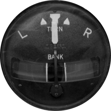
The turn and slip indicator (above) consists of a ball and needle; the ball indicates yaw (skid or slip), while the needle indicates direction and rate of turn.
The gyro of the turn and slip indicator spins around a horizontal axis whereby a turn causes precession and gyro movement, while a spring returns the gyro to neutral when the turn stops.
When the ball is centred, the needle markings indicate a standard rate turn of 3° per second. Thus a timed turn with the needle on the indicator will turn the aircraft 180° in one minute. The turn rate indicator (the needle deflection) is accurate only when the ball is centred with rudder (no yaw).
Most modern aircraft have a turn co-ordinator (depicted to the right) where the gyro is canted 35° and resultantly indicates turn rate irrespective of the ball position (yaw).1
The gyro for the attitude indicator spins about a vertical axis and provides pitch and bank information.
Most gyros require approximately 5 minutes to come to rotation speed.
References
1 Note the lower turn co-ordinator is indicated a standard rate turn to the left—if the bank is controlled precisely on the marker as shown, the aircraft will complete a 180° turn in 1 minute (3° per second)—this is a back-up manoeuvre for inadvertent flight into cloud (not dependent on vacuum gyros). Note the turn is balanced—no yaw is indicated if the ball is in the centre. If the ball deviates to left or right, the rule is to step on the ball using the rudder pedals, and this will produce directionally straight flight. Timed-turns (using the turn co-ordinator) is a feature of the Commercial Pilot program.
Further Readings: Flight Instruments