.jpg)


FLIGHT INSTRUMENTS
There are two flight-instrument systems, producing two types of flight instruments: pitot-static instruments and gyro instruments. You can think of them as families. The Pitot-Statics are an extraordinary lazy bunch. They are slow moving, and always lagging behind the action—you can’t always trust what they say. In contrast, the Gyro are a really honest bunch; they always keep up with the latest trends and are always on time—the Gyros are always in the centre of the action when it happens.
Pitot-static Instruments
The pitot-static system records static and dynamic air pressure, providing the pilot with information related to airspeed and altitude.
These pressures typically enter the system by way of ports located on the fuselage (static pressure sources) and the wing (dynamic pressure source).
Of the flight instruments which make use of the pitot-static system—the airspeed indicator (ASI), the vertical speed indicator (VSI), and the altimeter (ALT), only the ASI is connected to both pressure sources.
Airspeed Indicator
Connected to both the static and pitot (dynamic) ports, the ASI records the pressure difference (speed); each is measured by an expansion box referred to as an aneroid capsule.
At altitudes above 10000’ and at calibrated airspeed in excess of 200 KTS, an error in airspeed indications—referred to as compressibility error—will occur as a result of air being compressed at the pitot tube inlet. Compressibility error generally produces ASI readings that are too high.
There are three primary types of airspeed:
|
Indicated Airspeed (IAS) |
Uncorrected speed is read from the ASI. As altitude is increased, the ASI under-reads approximately 2% per 1000’. |
|---|---|
|
Calibrated Airspeed (CAS) |
IAS corrected for instrument and installation error; such errors are especially prominent in flights involving high angles of attack. Correction charts are usually found in the Pilot Operating Handbook. |
|
True Airspeed (TAS) |
CAS (usually IAS) corrected for air density (altitude and temperature); used primarily for flight planning groundspeed. Pressure altitude (discussed below), temperature, and IAS are entered on the appropriate flight calculator scales. (Note: the scales on E6B computer indicate CAS, rather than IAS, but should be interpreted as IAS for most practical purposes.) |
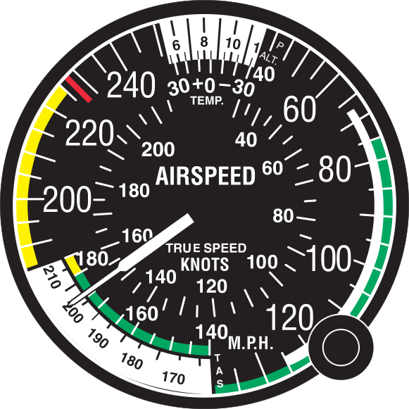
Here are the markings on an ASI:
| Red line | never-exceed speed (Vne). |
|---|---|
| Yellow arc | caution speed range, never to be intentionally entered, with the upper limit being Vne, and the lower limit being the maximum structural cruising speed (Vno). |
| Green arc | normal operating speed range, with the lower limit being the power-off stall speed, including flaps and gear up (Vsl), and the upper limit being Vno. |
| White arc: | flaps extension speed range—where flaps can be used, with the lower limit being the power-off stall speed with flaps and gear down (Vso), and the upper limit being the “maximum flaps extension speed” (Vfe). |
Note that manoeuvring speed (Va) is not indicated on the instrument.
Altimeter
The ALT is an airtight instrument case connected only to the static port; when the altitude of an aircraft increases, the pressure within the case decreases and a sealed aneroid capsule within the case expands, this expansion registered on the instrument face.
It is calibrated on the basis of ICAO Standard Atmosphere assumptions of standard sea level pressure (29.92” Hg), a pressure lapse rate of 1 inch per 1000’, and a standard temperature lapse rate (1.98°C per 1000’).
In the case that a static port becomes blocked during flight, most aircraft have an alternate static source switch in the cockpit that can be selected by the pilot.
If an altimeter indicates a 50’ error at sea level when set to the ALT pressure setting, the instrument is unserviceable; this tolerance increases with altitude (from ± 50’ at sea level to ± 230’ at 40000’).
There are two errors associated with the ALT: temperature errors and pressure errors. When flying from a high-pressure area to a low-pressure area, the ALT will read higher than actual altitude; similarly, when flying from warm air to cold air, the ALT will again read higher than actual altitude. “From high to low, watch out below.” “From warm to cold, watch out . .”
In addition to temperature and pressure errors, human error is not an uncommon cause of accidents. The effect of pressure is the same here, but the phraseology is slightly different: Too high subscale setting means a too high altimeter reading—that is, the aircraft would be at a lower level than is indicated, while too low subscale setting means a too low altimeter reading—that is, the aircraft would be at a higher level than is indicated.
The only time an altimeter will read an accurate or “true” altitude of an aircraft during flight is when ICAO Standard Atmosphere exists—an unlikely event.
When an altimeter set to the altimeter setting of an airport, the only time a pilot can be certain the altimeter is an accurate indication of “true” altitude is when the aircraft is on the ground at that airport.
Lag is associated with this instrument during climbs and descents (as a result of hysteresis, the period of time required for the aneroid to catch up to the changing pressure in the instrument case), and for this reason a good rule of thumb is to “lead” the altimeter indications—i.e., begin the levelling procedure with the necessary pitch inputs—using 10% of the vertical speed indications. For example, descending at 100’/min., the levelling inputs should be started 100’ above the target altitude.
There are five types of altitudes:
|
Indicated Altitude |
The reading on the altimeter when it is set to the current barometric pressure. |
|---|---|
|
Pressure Altitude |
The reading on the altimeter when it is set to standard pressure (29.92” Hg); this is used primarily in the calculation of aircraft performance and for calculating “true altitude.” |
|
Density Altitude |
Pressure altitude corrected for non-standard temperature, use primarily to predict aircraft performance during takeoffs. To calculate, the altimeter is set to 29.92” Hg (pressure altitude) and this figure entered on a flight computer on the appropriate scale. If an altimeter is not available, use the difference between standard pressure and the current altimeter setting; if the current pressure is lower than standard pressure, altitude is increased at a rate of 1000’ per 1-inch difference; if it is higher, the altitude is decreased. Aircraft performance graphs in the Pilot Operating Handbook usually provide a built-in calculation. |
|
True Altitude |
“Exact height above mean sea level.” This is used when a pilot wants the most accurate calculation of altitude—for example, when flying over mountainous regions. The current altimeter setting and elevation of the reporting station is noted. The pressure altitude of the aircraft is set into the E6B opposite ambient temperature (at altitude); the height of airspace lying between the aircraft (specifically, the indicated altitude) and the reporting station is then marked on the inner scale and the true altitude of that airspace is read on the outer scale. Finally, the true altitude figure is then added back to the reporting station’s elevation to give the aircraft’s true altitude. |
|
Absolute Altitude |
“Height of the aircraft above the surface of earth.” Not commonly used, unless the aircraft has radar. |
Vertical Speed Indicator
The final pitot-static instrument is the VSI, which indicates the vertical speed of the aircraft—i.e., the vertical component of the aircraft’s flight path—in hundreds of feet per minute. The sealed instrument case is connected to static pressure by way of a calibrated leak—i.e., a “slow bleeding” leak referred to as a restricted diffuser. Inside the case is a diaphragm that flexes in response to the pressure changes associated with a change in altitude; when the aircraft levels off, the diffuser equalizes the pressures on either side of the diaphragm causing the instrument readings to go to zero. The diffuser is designed to equalize pressures in approximately six to nine seconds.
The VSI is most accurate recording small changes in altitude, but becomes less accurate the greater the rate of descent or climb.
It is connected to the static port, so an alternate means of restoring static pressure for the altimeter if the static port becomes blocked is to deliberately break the glass on the VSI.
Malfunction of the Pitot-Static System
Instrument pilots are literally hanging from the pilot-static instruments. The penultimate line of defence is the gyro-system instruments, but if they fail or malfunction, survival depends on the expansion and contraction of the aneroid capsules which, in turn, give us very basic information concerning the aircraft’s attitude. In cloud, it is the pitot-static system which is, essentially, our lifejackets. So, you want to be smart with respect to possible malfunctions.
In the case of a sudden blockage of the static port , the ASI will under-read in a climb, and over-read in a descent. This is because there are no corrections for the pitot pressure with respect to vertical changes in air density. Conversely, in the event of a sudden blockage of the pitot tube (port), the ASI will over-read during a climb, and under-read during a descent. In this case, trapped pitot pressure is being overpowered by vertical changes in air density.
It should be kept in mind, however, that blockages can occur slowly—as would be the case, for example, in the case of gradual ice accumulations. As you would expect, a gradual reduction in pitot pressure will cause a slow reduction in indicated airspeed.
Here is a summary--remember the saying "SUC PUD" . . .
|
INSTRUMENT |
STATIC BLOCKAGE |
PITOT BLOCKAGE |
|
Altimeter |
Freezes at constant value. |
n/a |
|
Vertical-speed Indicator |
Freezes at zero. |
n/a |
|
Airspeed Indicator |
Under-reads in climb and over-reads in descent. |
Over-reads in climb and under-reads in descent. |
Gyro Instruments
There are three primary gyro instruments: heading indicator (HI), attitude indicator (AI), and the turn and slip indicator/turn co-ordinator.
All gyros consist of a spinning rotor held in a universal mounting or gimbals, which enables the rotor to remain in a constant position when the instrument casing is moved.
The spinning of the gyro is powered by two means. The HI and AI are driven by vacuum pressure (engine-driven or venturi). Engine-driven vacuum pressure is included among the pre-takeoff checks whereby the air pressure driving the gyro can be read in inches of mercury (“Hg.). By comparison, the gyros on the turn co-ordinator (or the older turn and slip indicator) is driven by an electric motor; if the electric motor provides insufficient RPMs to the gyro, a “flag” appears on the instrument display.
Most gyros require approximately 5 minutes to come to rotation speed.
In conditions of poor to zero visibility, it is impossible to fly an aircraft without flight instruments that depict pitch, roll, and yaw; in cloud, a pilot’s life rests with the correct function of these instruments. The electric/vacuum drive systems provide backup whereby all of the instruments cannot fail simultaneously. For added security, the gyro instruments are always checked during taxiing before takeoff.
Two principles affect all gyros: gyroscopic inertia (rigidity in space), and precession (perpendicular force on a gyro causes reaction 90° along the rotation direction).
The HI gyro spins around a horizontal axis and provides aircraft heading information; it is set to the aircraft compass.
Because of the earth’s rotation, the HI is subject to a precession error of approximately 3° every 15 minutes.
The AI gyro spins around a vertical axis and provides pitch and bank information.
The turn and slip indicator consists of a ball and needle; the ball indicates yaw (skid or slip), while the needle indicates direction and rate of turn.
The gyro of the turn and slip indicator spins around a horizontal axis whereby a turn causes precession and gyro movement, while a spring returns the gyro to neutral when the turn stops.
When the ball is centred, the needle markings indicate a standard rate turn of 3° per second. Thus a timed turn with the needle on the indicator will turn the aircraft 180° in one minute. The turn rate indicator (the needle deflection) is accurate only when the ball is centred with rudder (no yaw). This shortcoming is described in the Instrument Procedures Manual as follows:
It is important that both the needle and ball are used together. The problem associated with using these instruments separately is that although the ball will positively indicate that the aircraft is slipping or skidding, just which one of these the aircraft is doing can only be determined by reference to the needle. Furthermore, the needle will not positively indicate a bank attitude. An aircraft could be in a bank attitude and yet the needle could remain centred or indicate a turn in the opposite direction, if controls are not co-ordinated (P. 2-19).1
Most modern aircraft have a turn co-ordinator where the gyro is canted 35° and resultantly indicates accurate turn rate irrespective of the ball position (yaw).
Slip and Skid Indications
A slip occurs if the rate of turn is too slow for the angle of bank—the ball is displaced to the inside of a turn as there is a lack of centrifugal (outward) force.
A slip is corrected by decreasing the angle of bank or using rudder to increase the rate of turn (or a combination of both).
A skid occurs if the rate of turn is too fast for the angle of bank—in this case excessive centrifugal force pushes the ball to the outside of the turn.
A skid is corrected by increasing the angle of bank or using rudder to decrease the rate of turn (or a combination of both).
Turns and Turn Indications
When two aircraft are turning using the same angle of bank, the slower aircraft has the shorter turning radius and the highest rate of turn. For example, if two aircraft are turning using a 20° bank, the faster is travelling at 350 KTS, and the slower travelling at 130 KTS, the faster will take approximately 5.3 minutes to complete a 360° turn, while the slower will complete the same turn in only two minutes.
The relationship between radius of turn and airspeed varies exponentially—since the speed of a 350 knot aircraft is almost three-times faster than the speed of 130 knot aircraft, the radius of its turn will be approximately nine-times bigger than the radius required for the 130 knot aircraft.
Instrument Scanning
Control and Performance Instruments
For the purposes of instrument scanning, the standard panel array is divided into two groups—those instruments that provide information on the aircraft behaviour are referred to as performance instruments, while those instruments that are used to change the behaviour of the aircraft are referred to as control instruments. The performance instruments are the airspeed indicator, the turn co-ordinator, the heading indicator, the altimeter, and the vertical speed indicator, while control instruments are the attitude indicator and the manifold pressure or RPM gauge. Here is a summary:
When the performance instruments show unwanted change in performance, your attention must be directed to the control instruments to allow you to make the required changes. For example, if the performance instruments indicate that the heading or the altitude has changed, attention is directed to the control instruments (attitude indicator and/or tachometer) while adjusting attitude and power sufficiently to make a correction. You then confirm that the required correction is in progress by referring again to the performance instruments.2
It is in relation to the control and performance group that the statement “attitude plus power equals performance.” That is, if either the attitude indicator or manifold pressure indications are changed, corresponding changes in aircraft performance will result.
Selective Radial Scan
The concept of a Selective Radial Scan describes what is considered to be the most natural, yet practical pattern of instrument scanning. It draws attention to the fact that the attitude indicator is the hub of the scan pattern, and that the pilot must selectively move between supportive instrument displays depending on the flying tasks at hand. Accordingly, while attitude indicator information is supported by altimeter and heading indications in straight and level flight, the attitude indicator is supported by airspeed and heading indications during a straight climb.
Note that in straight and level flight the primary source for pitch information is the altimeter, while during climbs and descents pitch information is derived from the airspeed indicator.
Magnetic Compass
The compass is mounted usually in acid-free kerosene that dampens movement.
There are two primary errors associated with a compass—compass deviation and magnetic dip.
Compass deviation is deviation errors of the compass caused by the aircraft’s magnetic fields. It is checked regularly as part of aircraft maintenance. Effects of deviation are minimized by corrector magnets attached to the compass housing, while the remaining deviation errors are recorded and displayed in the cockpit on the compass deviation card.
Headings flown by the pilot are corrected for magnetic variations and for compass deviation.
The compass also has errors because of magnetic dip. At the earth’s equator, magnetic lines run parallel to the earth’s surface, but towards the north and south poles, the lines “dip” towards the surface and gradually become vertical. As the needle of a compass attempts to align itself with these descending magnetic lines, it too attempts to dip. To minimize this effect, the compass is mounted as a pendulum (“pendulous mounting”), but two errors remain related to magnetic dip—Northerly Turning Error, and the Acceleration/Deceleration Error.
The Northerly Turning Error occurs during shallow turns through southerly and northerly headings. As a rule, the compass “leads” when turning from southerly headings, and “lags” when turning from northerly headings. There is approximately no turning error when turning east and west headings.
The Acceleration/Deceleration Error occurs on easterly and westerly headings whereby acceleration causes the compass to show a northerly error, and deceleration causes a southerly error. Remember this by “ANDS.” There is approximately no such error on northerly and southerly headings.
Instrument Procedures Manual (Fourth Edition 1997), Transport Canada, Safety and Security.
Flight Training Manual (Fourth Edition), Transport Canada, Aviation (Gage Educational Publishing Company), P. 148.