AERODYNAMICS AND THEORY OF FLIGHT
- AERODYNAMICS AND THEORY OF FLIGHT
Forces of Flight
Lift
- Artificial forces manipulated by pilot.
- Generated through the wings.
- Acts perpendicular to the relative wind and wingspan.
- Lift is exerted through the centre of pressure.
- Opposes weight: during level cruise, lift equals weight; during climb, lift is greater than weight; and during descent, weight is greater that lift.
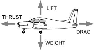
Weight
- Natural (uncontrollable) force generated by gravity (g force) that acts perpendicular to earth’s surface.
- Weight is exerted through the centre of gravity.
- Opposes lift (see above).
Thrust
- Artificial force manipulated by pilot and generated through engine(s) that acts horizontally, parallel to flight path.
- Opposes drag: when airspeed constant, thrust equals drag; when airspeed accelerating, thrust is greater than drag; and when decelerating, drag is greater than thrust.
Drag
- Natural resistance of aeroplane while moving through air, partially controlled by pilot.
- A horizontal force, parallel to flight path.
- Opposes thrust (see above).
Generating Lift

Airfoils
- Viewed as a cross-section: upper surface has more camber (curve) than lower surface.
- Chord line: straight line from leading edge to trailing edge.
- The airfoil generates lift by two means: pressure differential and ram air.
Bernoulli’s Theorem
Lift by pressure differential is based on the theory of Daniel Bernoulli: the faster a fluid flows (including air), the lower will be the pressure surrounding it.
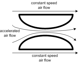
Given the difference of the camber of the upper and lower surfaces, the air passing over the foil has greater distance to travel than the air passing under the airfoil.
The air passing over must therefore travel faster than the air passing under the foil.
A low air-pressure region is created above the accelerated air flow.
The foil is displaced toward the lower pressure (upward) above the wing.
Ram Air
The pressure differential accounts for about 50% of the lift, while the remaining lift is generated by ram air.
Air is rammed under the foil, creating downwash, and upward pressure (Isaac Newton’s Third Law: the application of force causes an equal opposite force).
Angle of Attack
Lift varies with the angle of attack.

The angle of attack is the angle between the relative wind (parallel to flight path) and the chord line (line between leading and trailing edge).
Generally, the greater the angle of attack, the greater the lift.
Lift increases because the distance the air must flow along the upper camber increases, and the ram air and downwash increase.
An excessive angle of attack, referred to as the critical angle of attack, will produce a stall, where air-foil drag (induced drag) exceeds airfoil lift (usually 20°).
Drag
There are two types of drag: parasitic and induced.
Parasitic Drag
Parasitic drag is drag created by those parts of an aeroplane that do not contribute to lift—e.g., the tires, windshield, rivets, etc.
There are three forms of parasitic drag: form drag, skin-friction drag, and interference drag.
Form drag is caused by the frontal areas of the aeroplane, and is reduced by streamlining.
Skin-friction drag is caused by the air passing over the aeroplane surfaces, and is reduced by smoothing the surfaces (flush riveting, smooth paints, and waxing).
Interference drag is caused by the interference of airflow between parts of an aeroplane (wings and fuselage or fuselage and empennage) and is reduced by “filleting” interference areas).
Induced drag
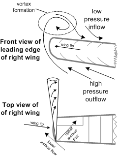
Induced drag is created by those parts of the aeroplane that creates lift—the wings and the horizontal tail surface.
Induced drag is said to be the by-product of lift.
The greater the angle of attack, the greater the induced drag.
Induced drag does not increase with speed; instead, as speed decreases induced drag increases.
Induced drag is associated with difference in pressure that exists above and below a wing surface; as airspeed decreases, and airfoil must produce an increased low pressure above the wing, and an increased high pressure below the wing; at the wing tip these disparate pressures meet in the form of a vortex as the high pressure flows around the wing tip is sucked into the low pressure above the wing; the greater the pressure differences (such as in the case in slower flight), the greater the vortices are at each wing tip, and the greater the drag caused by these vortices.
Ground effect is a term used to described the reduced drag and increased lift experience when an aircraft is flying close to the ground—as is the case, for example, during landings and takeoffs; the reduced drag associated with ground effect is the result of the ground interfering with the formation of the wing tip vortices.
Ground effect exists when the aircraft is within one wingspan distance from the ground, but is most effective at distances equal or less than ½ wingspan (i.e., ½ the distance between the wingtips).
Wing tip vortices can produce extremely hazardous turbulence and there are crucial operational considerations (see page 70).
Boundary Layer
Along the upper camber of an airfoil, there are two types of airflow: turbulent and laminar (smooth).
The turbulent and laminar flows are separated by a point of transition, or separation point.
As the angle of attack is increased the portion of the upper airflow that is turbulent also increases (it migrates forward from the trailing edge).
Aileron Drag
A type of adverse or undesirable yaw is aileron drag; aileron drag is created when a pilot manipulates the ailerons when rolling into a turn.
When the pilot induces a roll, one aileron is deflected upward so as to decrease the angle of attack associated with that portion of the wing, the same portion of the opposite wing is subject to an increase in the angle of attack as the aileron is deflected downward.
As the downward deflected aileron enters the high-pressure airflow below the wing it creates drag that causes the wing to move rearward; the upward moving aileron enters low-pressure airflow and is subject to less drag and allowing this wing to move forward.
Aileron drag can be reduced by flap design, including Differential Ailerons (in which the movement of the downward aileron is reduced relative to the aileron that is deflected upward), and Frise Ailerons (in which the upward deflected aileron projects the forward portion of the aileron structure into the airflow below the wing).
Aileron drag can be controlled by the use of sufficiently adequate opposite rudder during the rolling movement.
Stalls
Stalls occur at the critical angle of attack, at which point the airflow over the wing becomes chaotic and the wings can no longer produce sufficient lift to counteract weight.
As the airfoil approaches the stalling speed, the point of transition, or separation point, moves forward enough to exceed the design factor of the wing.
The stalling angle is usually 20°. Since most aircraft lack angle-of-attack indicators, airfoil angle is measured by indicated airspeed (IAS).
As a rule, aircraft will usually stall near the stalling speed published in the Pilot Operating Handbook (bottom of green line on an Airspeed Indicator); however, IAS does not always indicate angle of attack, as in the case of a high-speed stall.
Factors that affect the Stall
Snow, frost, ice and dirt:
All of these disrupt the laminar flow and therefore reduce airfoil lift capability. It is illegal to fly with snow, frost, or ice adhering to “critical surfaces” of the aircraft1— “wings, control surfaces, rotors, propellers, horizontal stabilizers, vertical stabilizers or any other stabilizing surface of an aircraft.” Contamination to the extent of medium to coarse sandpaper will reduce lift by 30% and increase drag by 40%.
Weight
Increased weight requires increased lift; therefore the critical angle of attack (stall) will occur at higher airspeeds. Stated another way, if two aircraft are travelling at the same airspeed, but one is heavier than the other, the angle of attack of the heavier aircraft is greater than the lighter aircraft and therefore that much closer to the critical angle of attack.
Centre of Gravity
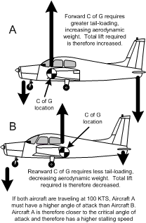
Stalling speed increases as the aircraft C of G moves forward. As the C of G moves forward, the negative lift generated by the horizontal tail surface will have to be increased. Any increase in the negative lift produced by the tail will effectively increase the aerodynamic weight of the aircraft—producing the same effect as described above with respect to weight. Conversely, stalling speeds decrease as the C of G moves aft as less negative lift is required from the tail and the aircraft is aerodynamically lighter. While the benefits of a rearward C of G is a lower stall speed, the adverse result of a rearward C of G is less stability as there is less tail force that can be manipulated by the pilot through elevator or stabilator control.
Turbulence
Upward vertical gusts abruptly increase the angle of attack beyond the stalling angle, irrespective of airspeed.
Turns
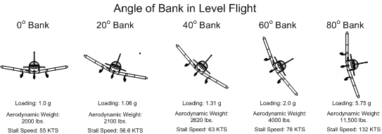
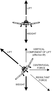
During a turn in level flight, greater lift is required to offset increased effective aerodynamic weight of the aircraft in the turn. Because the angle of attack of an aircraft must be increased to offset the increased aerodynamic weight (resultant force of a turn), the wing is closer to the critical angle of attack and therefore closer to a stall, despite a constant airspeed.
Accordingly, there is an increase in the relative stall speed of an aircraft in a level turn. The formula to determine increased stall speed is as follows: normal stalling speed times the square root of the load factor equals banked stall speed. Thus, an aircraft with a stall speed of 50 KTS and in a 60°-bank turn (load factor of 2.0) will stall at 71 KTS.
Flaps
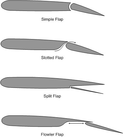
An increase in airfoil lift is produced by the use of flaps, and the stall speed is decreased by their use (bottom of white line on an Airspeed Indicator). The extension of flaps has the effect of increasing the relative angle of attack of the airfoil. Induced drag is also increased. Some flap designs incorporated slots, which permit the compressed air under the wing to migrate through the slot to the upper surface of the flaps. These are referred to as slotted flaps. Some flap designs allow the flap surface to move rearward as it extends—the feature is referred to as a Fowler Flap.
Spins
Spinning is defined as autorotationthat develops after an aggravated stall (a wing dropping during a stall).
The downward moving wing has a higher angle of attack and more induced drag than the upward moving wing and therefore acquires a greater stalled condition. Spinning involves simultaneous roll, yaw and pitch as it develops a helical or corkscrew path nose down.
An incipient spin is the autorotation prior to a vertical descent path, while a fully developed spin begins once the vertical helical or corkscrew path is achieved.
Lift-drag ratio
The amount of lift/induced drag can be graphically plotted (lift/drag coefficients vs. angle of attack).
As the angle of attack increases, lift increases to the critical angle of attack, and then falls off suddenly.
As the angle of attack increases, induced drag increases slowly at first, and then in ever increasing proportions.
The lift-drag ratio defines the proportion of lift to drag at given angles of attack.
The study of an aircraft’s lift-drag ratio helps engineers map out the maximum range and maximum glide-distance configurations.
Wing Design
There are numerous wing-design features that affect performance: laminar versus conventional airfoils, angle of incidence, washout, stall strips, and airfoil variation.
Laminar and conventional airfoils

There are two types of airfoils commonly used in wing design: laminar and conventional.
As a rule, the laminar foil is faster, but the cost is more adverse stalling characteristics.
They differ with respect to location of the maximum camber: while the maximum camber on a conventional airfoil is located 25% behind the leading edge, the laminar maximum camber is located at 50% chord.
On the laminar foil, a greater portion of the upper camber is dedicated to laminar airflow, and there is therefore less drag; the cost of this, however, is that the transition or separation point “jumps” rapidly forward at the approach of a stall; additionally, the laminar foil is more susceptible to surface contamination.
Angle of incidence

Defined as the angle between the chord line and the longitudinal axis of the aeroplane; designers select an angle that provides optimum lift/drag ratio.
Washout
A design trait that pacifies or softens the stall characteristics of an aeroplane whereby the wings are “twisted” such that the wing tips have a lower angle of incidence than the wing root.
The effect is that the entire wing will not stall simultaneously; instead, the stall will progressively move from the roots to the tips.
Because the wing tips are the last to stall, the ailerons will remain effective longer during the stall.
Stall Strips
Stall strips are triangular strips placed on a portion of the leading edge of wing.
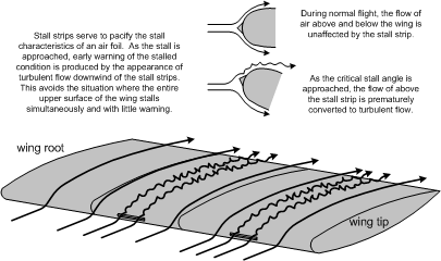
Stall strips create a gentle stall because the portions of the wing behind the strips stall first.
Airfoil Variation
This involves spanwise airfoil variation whereby a thin high-speed airfoil is designed near the roots, and a low-speed airfoil near the tips.
The high-speed roots stall before the low-speed tips.
Stability
Aeroplane movement is based on 3 axes: the vertical (normal) axis, the lateral axis, and the longitudinal axis.
All three axes pass through the aircraft C of G.
Stability is defined as the tendency of an aircraft to return to, stay at, or move farther from its original attitude after it has been displaced. There is positive, neutral, and negative stability.
Longitudinal
Movement around the longitudinal axis is roll, which produces bank, and is produced by the ailerons.
Longitudinal stability (of the axis) is provided by a nose-heavy design and a “negative-lift” tail.
Lateral
Movement around the lateral axis is pitch, and is produced by the elevator.
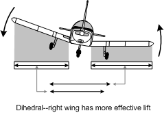
Lateral stability (of the axis) is provided by dihedral, which lowers C of G relative to the lifting surfaces (wing tips are positioned higher than the wing roots). Additionally, the lower wing produces more effective lift than the raised wing, causing the lower wing to naturally rise, and higher wing to descend.
Directional
Movement around the vertical (normal) axis is yaw, and is “controlled” by the rudder.
Adverse yaw takes place during rolling movement because of aileron drag, and is controlled by rudder.
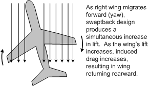
Stability of the vertical axis is referred to as directional stability, and is produced by the vertical stabilizer and sweptback (sweepback) wing design. When a sweptback wing moves forward, it acquires increased lift, as the airflow is more perpendicular to the wing’s leading edge. This increased lift simultaneously produces increased induced drag, which encourages the wing to migrate back to is original position. The effect is the reverse for the opposite wing.
Forces during Takeoff
There are a number of forces exerted on the aircraft during the take-off roll and climb, and they all contribute (in single-engine aircraft) to left yaw tendencies, which must be controlled by the pilot with the used of rudder pedals.
Torque
The force of Torque is based on the principle of physics that a movement in one direction will cause a movement in the opposite direction. The force referred to here is the force of the spinning propeller which, from the pilot perspective in the cockpit, rotates clockwise. This movement of the propeller produces an opposite rotation of the aircraft—from the pilot perspective, counter-clockwise. This translates during the takeoff roll as a left-yaw tendency, and requires the pilot to exert right-rudder pressure.
Precession
Precession is a gyroscopic force, which again originates from the movement of the propeller. According to the law of precession, a pressure exerted on a spinning mass will cause a reaction 90° along the direction of rotation. The force of precession during takeoff is primarily associated with conventional-gear (“tail-dragger”) aircraft, with the pilot exerting nose-down pressure on the control column to raise the tail wheel off the ground—when this happens, the spinning propeller converts this force into a left-yaw movement, which again must be countered by the pilot with right-rudder input.
Slipstream
Slipstream refers to the spiral-like movement of the air flowing from the propeller over the fuselage of the aircraft. The spiral flow migrates around the fuselage as it travels rearward and strikes the left side of the vertical fin. This again translates to the pilot as left-yaw tendency, which must also be countered with right rudder.
Asymmetric thrust
The force referred to as asymmetric thrust must be managed by the pilot whenever a single-engine aircraft is in a climb or nose-up attitude. When the longitudinal axis of the aircraft is inclined upward, the propeller produces different levels of thrust whereby the down-going blade (the right side of the spinning propeller disk, as viewed by the pilot) produces more thrust than the up-going blade (the left side of the propeller disk). The relative wind (or flight path) of the aircraft with a nose-up attitude means that the down-going blade has a greater angle of attack (and therefore greater thrust) than the down-going blade (which has a less angle of attack). A pilot learns that whenever the aircraft is in a nose-up attitude—whenever the aircraft is climbing—compensating right rudder must be used to counter the resultant left-yaw tendency.
Climbs
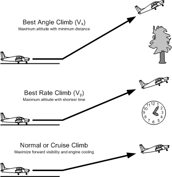
There are three climb configurations commonly used in flying. The climb configurations are flown on the basis of air speeds (the pilot’s indication of angle of attack), and these speeds, as well as the associated flap configurations, are specified by the aircraft manufacturer in the Pilot Operating Handbook.2 They are summarized as follows:
Best Angle Climb (Vx)
The best angle climb speed provides the greatest gain in altitude over a given distance. This speed would be used, for example, when the pilot must clear obstacles that exist off the end of a runway. An aircraft manufacturer usually specifies that partial flap settings must be used when flying best angle speed—with the Piper Cherokee, 25° flaps are required.3
Best Rate Climb (Vy)
The best rate climb speed provides the greatest gain in altitude over a given period of time—it will get you to the highest altitude the quickest. This speed is typically flown immediately after rotation during a takeoff where pilots, not faced with obstacle clearance concerns, typically seek to get safely clear of the ground as quickly as possible during a departure.
Normal or Cruise Climb
The normal climb speed is usually specified by the manufacturer to combine efficiency in climb performance with effective cooling of the engine (the steeper the angle of attack, the less effective the airflow over the engine). This speed is usually flown after the airport departure is completed—say 1000’ AAE4—and obstacles are no longer a factor. The total time en route is decreased when a normal or cruise climb is flown.
References
1 CAR 602.11
2 Interestingly, two of these climbs speed—Vx and Vy—must be quoted by a pilot candidate during the oral examination that precedes the actual flight test—the three other speeds that must be quoted from memory are the stall speed, landing configuration (Vso), stall speed, clean configuration (Vsl), and manoeuvring speed (Va).
3 By comparison, Piper specifies that 40° flaps (full) should be used for landings.
4 “AAE” means “Above Aerodrome Elevation.”
.jpg)

